![]()
Building and Running the UART Bootloader applications
Downloading and building the application
To clone or download this application from Github,go to the main page of this repository and then click Clone button to clone this repo or download as zip file. This content can also be download using content manager by following these instructions
Path of the application within the repository is apps/uart_bootloader/
To build the application, refer to the following table and open the project using its IDE.
Bootloader Application
| Project Name | Description |
|---|---|
| bootloader/firmware/pic32mk_mcj_curiosity_pro.X | MPLABX Project for PIC32MK MCJ Curiosity Pro Development Board |
Test Application
| Project Name | Description |
|---|---|
| test_app/firmware/pic32mk_mcj_curiosity_pro.X | MPLABX Project for PIC32MK MCJ Curiosity Pro Development Board |
Setting up PIC32MK MCJ Curiosity Pro Development Board
- Install an USB UART click board on to the mikroBUS Xplained Pro board
- Connect the mikroBUS Xplained Pro board to the J501 header of the PIC32MK MCJ Curiosity Pro Development Board
- Connect mini USB cable to the USB UART click board. This will enumerate the USB to UART port
- For programming, Connect micro USB cable to the ‘Debug USB’ connector(J1) on the board to the computer
Setting up the host script
- Refer to Bootloader Host Script Help for setting up the btl_host.py utility used to send the application binary from host PC
Running the Application
- Open the test application project test_app/firmware/pic32mk_mcj_curiosity_pro.X in the IDE
- Build the project to generate the binary (Do not program the binary)
- Open the bootloader project bootloader/firmware/pic32mk_mcj_curiosity_pro.X in the IDE
-
Build and program the application using the IDE
-
Run the btl_host.py from command prompt to program the application binary
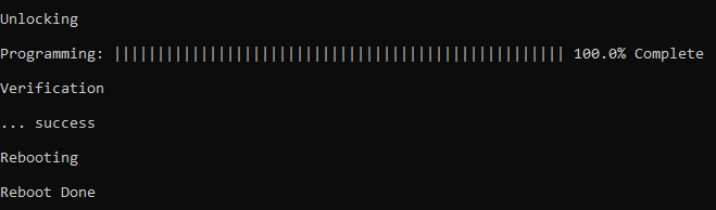
python <harmony3_path>\bootloader\tools\btl_host.py -v -i <COM PORT> -d pic32mk -a 0x9D000000 -f <harmony3_path>\bootloader_apps_uart\apps\uart_bootloader\test_app\firmware\pic32mk_mcj_curiosity_pro.X\dist\pic32mk_mcj_curiosity_pro\production\pic32mk_mcj_curiosity_pro.X.production.bin - Following snapshot shows output of successfully programming the test application
- Rebooting and Reboot Done messages in below output signifies that bootloading is successful
- If above step is successful then the LED2 should start blinking
- Open the Terminal application (Ex.:Tera Term) on the computer
- Configure the serial port settings as follows:
- Baud : 115200
- Data : 8 Bits
- Parity : None
- Stop : 1 Bit
- Flow Control : None
- Reset or Power cycle the device
-
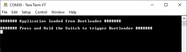
LED2 should start blinking and you should see below output on the console
-
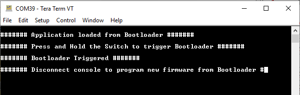
Press and hold the Switch SW200 to trigger Bootloader from test application and you should see below output
- Repeat Steps 5-11 once and jump to Step-14.
- This step is to verify that bootloader is running after triggering bootloader from test application in Step 12
- Press and hold the Switch SW200 and then press Reset button or Power cycle the device to force trigger bootloader at startup
- Repeat Steps 5-11 once
- This step is to verify whether bootloader is triggered by switch press at reset
Additional Steps (Optional)
-
To bootload any other application refer to Application Configurations
-
Once done repeat the applicable steps mentioned in Running The Application